Actuators with ball screw drive
Features
Linear actuators MKUVE..-KGT and MKUSE..-KGT comprise:
- a carriage unit
- a linear recirculating ball bearing and guideway assembly
- a support rail
- a ball screw drive available with various pitch values
- one locating bearing and non-locating bearing unit
- two sets of bellows.
- with several, non-driven carriage units
- with a linear recirculating ball bearing and guideway assembly and ball screw drive with anti-corrosion protection
- with bellows resistant to welding beads
- with a rolled ball screw spindle to accuracy class 25 μm/300 mm
- with a trapezoidal screw drive
- without bellows
- with an extended carriage unit
- with compressed air connections in the support rail
- with a locating bearing arrangement having increased load capacity
- with special machining.
- support rail unit comprising carrier profile and guideway
- support spacings up to 5 850 mm
- introduction of the load at the centre of the carriage unit if this is at the centre point between the bearing points.
- lithium soap or lithium complex soap grease with base oil having a mineral oil base
- special anti-wear additives for loads C/P < 8, indicated by “P” in the DIN designation
- base oil viscosity ISO VG 68 to ISO VG 100
- consistency in accordance with NLGI grade 2.
- the travel velocity of the actuator carriage unit
- the load
- the operating temperature
- the stroke length
- the environmental conditions and environmental influences
- the mounting position.
- spindle length
- spindle diameter
- spindle bearing arrangement
- mounting method.
- location of the support rail on the adjacent construction
- mounting of the components to be moved on the carriage unit or carriage units.
- the travel velocity of the carriage unit
- the load
- the temperature
- the stroke length
- the environmental conditions and influences.
Actuators MKUVE..-KGT and MKUSE..-KGT are linear units for positioning, handling and machining tasks. They have a guidance system that is wear-resistant and clearance-free. The drive elements are mounted in a self-supporting support rail. The actuators are supplied in a length specific to the application and in a configuration specific to the customer.
The ball screw drive with a driven spindle gives a balanced combination of economical and technical characteristics, even in the design with a single nut.
In the case of series MKUVE..-KGT, the carriage unit is guided by means of two four-row carriages of the linear recirculating ball bearing and guideway assembly KUVE arranged in series.
In the case of series MKUSE..-KGT, the carriage unit is guided by means of two six-row carriages of the linear recirculating ball bearing and guideway assembly KUSE arranged in series.
Accessories available for the actuators include fasteners and connectors, couplings and coupling housings and electric drive components such as motors, motor/gearbox units and controllers.
The advantage of the actuator MKUSE..-KGT is a significantly longer operating life under the same load compared with the actuator MKUVE..-KGT.
Designs
These linear actuators with a four-row linear recirculating ball bearing and guideway assembly (MKUVE) or six-row linear recirculating ball bearing and guideway assembly (MKUSE) are available in various designs, see table.
Available designs
|
Suffix |
Description |
Design |
|---|---|---|
|
‒ |
One driven carriage unit |
Basic design |
|
SPU |
One spindle support |
Standard |
|
2SPU |
Two spindle supports |
Standard |
|
WN2 |
Second, non-driven carriage unit |
Standard |
|
N |
Fixing slots in carriage unit |
Standard |
|
OA |
Without ball screw drive |
Standard |
Special designs are available by agreement. Examples of these are linear actuators:
Carriage unit
The carriage unit in series MKUVE..-KGT comprises a carriage housing made from anodised profiled aluminium, a lubrication distributor and the two KWVE carriages of the linear recirculating ball bearing and guideway assembly, ➤ Figure and table.
The carriage unit in series MKUSE25..-KGT comprises an anodised aluminium plate, two end plates and two KWSE carriages of the linear recirculating ball bearing and guideway assembly, see table.
If higher moment loads must be supported, the actuator is available with a second, non-driven carriage unit. It is connected to the driven carriage unit by means of the adjacent construction.
Lengths of carriage units
|
Series |
Carriage unit length |
Suffix |
|---|---|---|
|
mm |
||
|
MKUVE15..-KGT |
160 |
160 |
|
MKUVE20..-KGT |
200 |
200 |
|
MKUSE25..-KGT |
200 |
200 |
Carriage unit

Bellows
The bellows fitted as standard protect the screw drive and guidance system against contamination. They are guided in the support rail and, as a result, the actuator is also suitable for applications involving an overhead arrangement.
Lubrication
In the case of linear actuators of series MKUVE..-KGT, the carriage unit is equipped with a lubricant distributor. This allows relubrication of the carriages and spindle nut.
In the case of the linear actuator of series MKUSE25..-KGT, the carriages and spindle nut are relubricated via the end plate on the locating bearing side of the carriage unit.
Sealing
The carriages are sealed.
Location
For location on the adjacent construction, the carriage unit in series MKUVE..-KGT has two T-slots, with centrally positioned filling slots.
For location on the adjacent construction, the carriage unit in series MKUSE25..-KGT has threaded holes.
Support rail unit
The support rail unit is a composite unit comprising a carrier profile made from anodised aluminium and the guideway of a four-row linear recirculating ball bearing and guideway assembly KUVE (actuator series MKUVE..-KGT) or of a six-row linear recirculating ball bearing and guideway assembly KUSE (actuator series MKUSE..-KGT). The linear recirculating ball bearing and guideway assemblies are preloaded clearance-free and run without stick-slip.
Since the support rail has very high bending rigidity, it can be used to span large gaps.
Support rail length
The maximum length of the support rails in the case of MKUVE..-KGT is 5 850 mm. In the case of MKUVE..-KGT/50..-N, the maximum length of the support rail is 2 900 mm.
T-slots
Support rails and carriage units have T-slots for standardised T‑nuts. These are used in order to fix the actuators to the adjacent construction.
Ball screw drive
The spindle has a rolled thread and, depending on the diameter, up to four pitch values per spindle size are available, see table.
As standard, single nuts with an axial clearance dependent on the pitch are used, see table. Preloaded double nuts are available for the pitch values 5 mm, 10 mm and 20 mm.
The spindle is supported on the locating bearing side by an axial angular contact ball bearing ZKLN or ZKLF. The bearings are greased for life.
The screw drive and guidance system are protected against contamination by bellows.
One or two spindle supports can be fitted.
Ball screw drive variants
|
Screw drive variants |
Suffix |
||
|---|---|---|---|
|
Pitch |
5 |
mm |
5 |
|
10 |
mm |
10 |
|
|
20 |
mm |
20 |
|
|
40 |
mm |
40 |
|
|
50 |
mm |
50 |
|
|
Single flanged nut |
F |
||
|
Double nut |
FM |
||
|
Single nut (cylindrical) |
M |
||
|
Double nut (cylindrical) |
MM |
||
|
Without drive (no spindle), with bellows |
OA |
||
Permissible spindle speed
For data on the maximum spindle speed, see pages starting link.
For longer actuators, the permissible spindle speed can be increased by the use of one or two spindle supports (suffix SPU or 2SPU). These supports, arranged in pairs, can be moved as required. They are moved by the driven carriage unit.
Locating and non-locating bearing unit
The locating bearing unit supports the axial forces acting on the ball screw drive. It comprises an end plate made from anodised aluminium and an axial angular contact ball bearing ZKLN or ZKLF.
The non-locating bearing unit comprises an anodised aluminium end plate. This contains a needle roller bearing with an extended inner ring for compensation of possible length increases between the support rail and the ball screw drive.
Spindle support
Actuators MKUVE15..-KGT with a total length of more than 800 mm, MKUVE20..-KGT with a total length of more than 1 000 mm and MKUSE25..-KGT with a total length of more than 1 200 mm can be fitted with movable spindle supports (suffix SPU or 2SPU).
Drive elements
For the actuators, Schaeffler also offers components such as couplings, coupling housings and planetary gearboxes as well as servo motors and servo controllers, ➤ Figure.
Linear actuator with drive elements


Proven drive combinations
ATTENTION
The bearing load in the actuators must be checked; it is not taken into consideration in dimensioning of the motor. For vertical mounting, motors with a holding brake must be used.
If different loading and kinematic criteria apply, the least favourable operating conditions should be used for calculation of the drive motor and design of the gearbox, coupling and servo controller.
Mechanical accessories
A large number of accessories are available for linear actuators with monorail guidance system and ball screw drive. The allocation of accessories is valid if the data match the Technical principles and the Design and safety guidelines, link.
Allocation
|
Linear actuator / size |
MKUVE..-KGT-N |
15 |
20 |
||
|---|---|---|---|---|---|
|
MKUSE..-KGT |
25 |
||||
|
Fixing brackets |
|||||
|
WKL-48×48×35 |
‒ |
‒ |
|
||
|
WKL-65×65×30-N |
|
|
|
||
|
WKL-65×65×35 |
‒ |
‒ |
|
||
|
WKL-65×65×35-N |
‒ |
|
|
||
|
WKL-90×90×35-N |
‒ |
|
|
||
|
WKL-98×98×35 |
‒ |
‒ |
|
||
|
Clamping lugs |
|||||
|
SPPR-10,5×20 |
|
‒ |
‒ |
||
|
SPPR-13,5×20 |
|
|
‒ |
||
|
SPPR-24×20 |
|
‒ |
‒ |
||
|
SPPR-23×30 |
‒ |
|
‒ |
||
|
SPPR-28×30 |
‒ |
‒ |
|
||
|
T-nuts |
|||||
|
|
MU-DIN 508 M4×5 |
|
‒ |
‒ |
|
|
MU-M3×5
|
|
‒ |
‒ |
||
|
MU-DIN 508 M6×8 |
‒ |
|
|
||
|
MU-M4×8
|
‒ |
|
|
||
|
T-nuts made from corrosion-resistant steel |
|||||
|
MU-DIN 508 M4×5-RB |
|
‒ |
‒ |
||
|
MU-DIN 508 M6×8-RB |
‒ |
|
|
||
|
T-bolts |
|||||
|
SHR DIN 787-M5×5×25 |
|
‒ |
‒ |
||
|
SHR DIN 787-M8×8×32 |
‒ |
|
|
||
|
Rotatable T-nuts |
|||||
|
|
MU-M3×5-RHOMBUS |
|
‒ |
‒ |
|
|
MU-M4×8-RHOMBUS |
‒ |
|
|
||
|
MU-M6×8-RHOMBUS |
‒ |
|
|
||
|
Positionable T-nuts |
|||||
|
|
MU-M4×5-POS |
|
‒ |
‒ |
|
|
MU-M5×5-POS |
|
‒ |
‒ |
||
|
MU-M4×8-POS |
‒ |
|
|
||
|
MU-M5×8-POS |
‒ |
|
|
||
|
MU-M6×8-POS |
‒ |
|
|
||
|
MU-M8×8-POS |
‒ |
|
|
||
|
|
Suitable. |
Allocation
|
Linear actuator / size |
MKUVE..-KGT-N |
15 |
20 |
||
|---|---|---|---|---|---|
|
MKUSE..-KGT |
25 |
||||
|
Hexagon nuts |
|||||
|
MU-ISO 4032 M4 |
|
|
‒ |
||
|
MU-ISO 4032 M5 |
|
‒ |
‒ |
||
|
MU-ISO 4032 M8 |
‒ |
|
|
||
|
T-strips |
|||||
|
LEIS-M4/5-T-NUT-SB-ST |
|
‒ |
‒ |
||
|
LEIS-M4/5-T-NUT-HR-ALU |
|
‒ |
‒ |
||
|
LEIS-M6/8-T-NUT-SB-ST |
‒ |
|
|
||
|
LEIS-M8/8-T-NUT-SB-ST |
‒ |
|
|
||
|
LEIS-M6/8-T-NUT-HR-ST |
‒ |
|
|
||
|
LEIS-M6/8-T-NUT-HR-ALU |
‒ |
|
|
||
|
LEIS-M4/5-T-NUT-ST |
|
‒ |
‒ |
||
|
LEIS-M6/8-T-NUT-ST |
‒ |
|
|
||
|
Connector sets (parallel connectors) |
|||||
|
VBS-PVB8 |
‒ |
|
|
||
|
VBS-PVB8/10 |
‒ |
|
|
||
|
Slot closing strips |
|||||
|
NAD-5×5,7 |
|
‒ |
‒ |
||
|
NAD-8×4,5 |
‒ |
|
|
||
|
NAD-8×11,5 |
‒ |
|
|
||
|
|
Suitable. |
|
|
Suitable and T-strips must already have been inserted at the time of despatch. |
Design and safety guidelines
Load carrying capacity and load safety factor
The load carrying capacities and load safety factors to be observed differ as a function of the mounting position.
Deflection
The deflection of linear actuators is essentially dependent on the support spacing, the rigidity of the support rail, the adjacent construction and the bearing arrangement. As the rigidity of these components increases, the deflection of the actuators is reduced.
Diagrams
The diagram values are determined for a bearing arrangement or clamping which is in theory infinitely rigid and are subdivided into locating/non-locating and locating/locating bearing arrangements, starting ➤ Figure.
The deflection of the support rail is valid under the following conditions:
ATTENTION
The diagrams represent guide values only for the deflection of the support rail, starting ➤ Figure. The effect of deflection on the rating life of the guidance system is not taken into consideration.
It is not possible to provide deflection diagrams for actuators with a second, non-driven carriage unit since there will be different spacings between the carriage units. In such cases, please consult the Schaeffler engineering service.
Deflection about the z axis

Deflection about the z axis

Deflection about the y axis

Deflection about the y axis

Deflection about the z axis

Deflection about the z axis

Deflection about the y axis

Deflection about the y axis

Deflection about the z axis

Deflection about the z axis

Deflection about the y axis

Deflection about the y axis

Deflection about the z axis

Deflection about the z axis

Deflection about the y axis

Deflection about the y axis

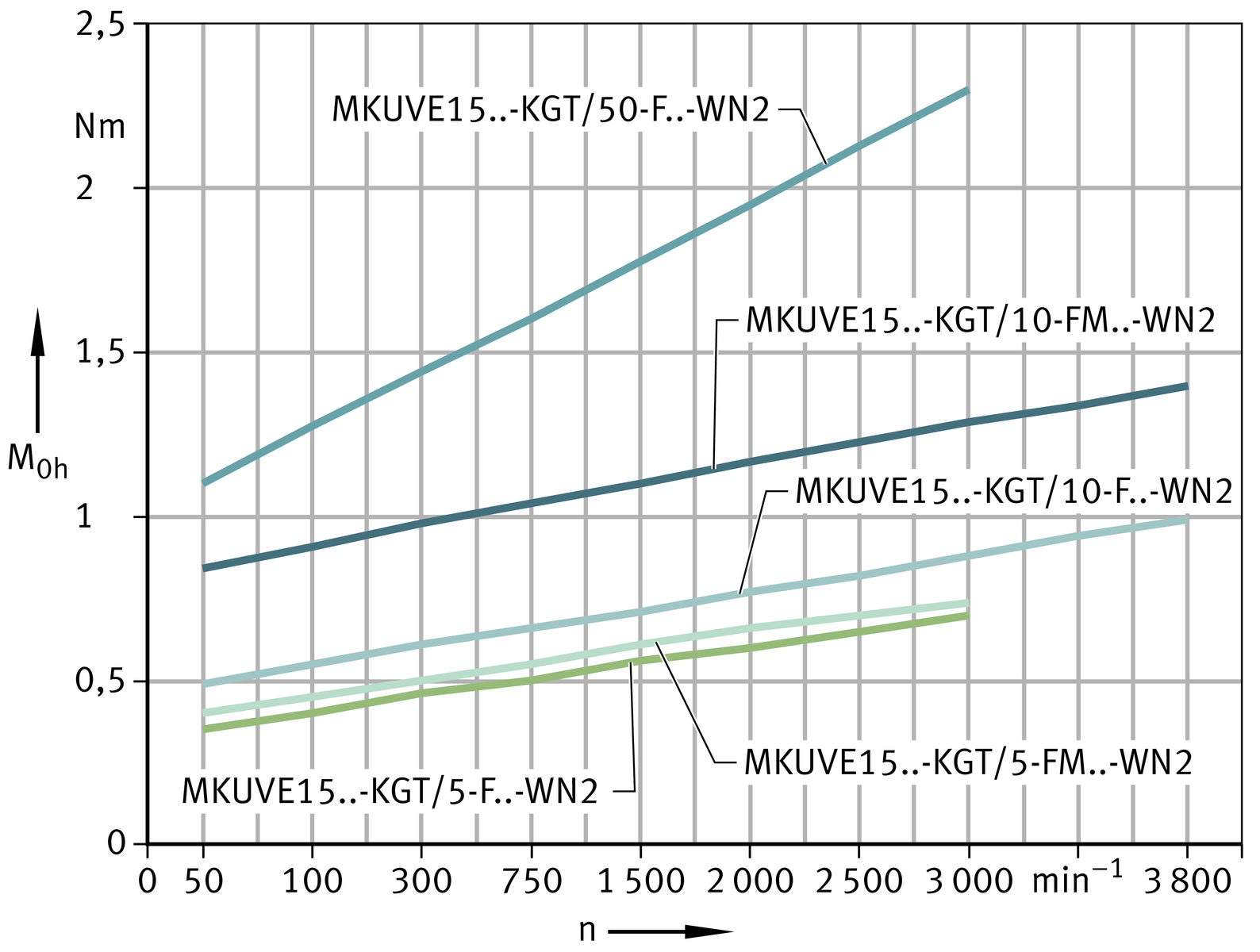
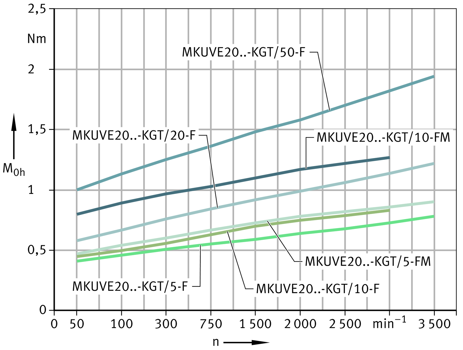
Idling drive torque
The idling drive torque M0 of linear actuators with screw drive is calculated as a function of the spindle speed and the horizontal (M0h) or vertical (M0v) mounting position. The idling drive torque increases with increasing travel velocity.
Idling drive torque
Horizontal mounting position

Idling drive torque
Vertical mounting position

Idling drive torque
Horizontal mounting position
Idling drive torque
Vertical mounting position

Idling drive torque
Horizontal mounting position
Idling drive torque
Vertical mounting position

Idling drive torque
Horizontal mounting position

Idling drive torque
Vertical mounting position

Idling drive torque Horizontal mounting position

Idling drive torque
Vertical mounting position

Idling drive torque Horizontal mounting position

Length calculation of actuators
The length calculation of actuators is based on the required effective stroke length NH . The effective stroke length NH must be increased by the addition of safety spacing values on both sides of the travel distance.
The total length Ltot of the actuator is determined from the support rail length L2 and the lengths of the end plates L4 and L5. If two carriage units are present, both carriage unit lengths L and the spacing Lx1 must be taken into consideration.
If spindle supports are used, size 25 must be calculated using a larger effective length factor, see table.
Parameters for length calculation
| GH | mm |
Total stroke length |
| NH | mm |
Effective stroke length |
| S | mm |
Safety spacing, for minimum values see table |
| L | mm |
Length of carriage plate |
| L2 | mm |
Length of support rail |
| L4 | mm |
Length of end plate |
| L5 | mm |
Length of end plate |
| Ltot | mm |
Total length of actuator |
| Lx1 | mm |
Spacing between two carriage units |
| FBL |
Effective length factor according to actuator type |
|
| FBL SPU |
Effective length factor for spindle support according to actuator type. |
Total stroke length
The total stroke length GH is determined from the required effective stroke length and the safety spacings, which must correspond to at least the spindle pitch P.

Support rails
Actuators with monorail guidance system and ball screw drive are only available with a single-piece support rail. The maximum length of a support rail is 5 850 mm. In the case of actuators MKUVE15..-KGT/50, the maximum length of the support rail is 2 900 mm.
Spacing Lx1 between carriage units
The minimum spacing Lx1 min between two carriage units is 20 mm.
Total length Ltot and support rail length L2
The following ➤ equtions are designed for one and two carriage units. The parameters and their position can be found in ➤ Figure, ➤ Figure and the table. If more than two carriage units are present, please contact us.
Length parameters for one carriage unit

One carriage unit with bellows

Total length with drive

Total length without drive

Length parameters for two carriage units

Two carriage units with bellows

Total length with drive
Total length without drive
Length parameters
|
Designation |
L |
L4 |
L5 |
S |
FBL |
FBL SPU |
|---|---|---|---|---|---|---|
|
mm |
mm |
mm |
mm |
|||
|
MKUVE15-160-KGT/5-N |
160 |
25 |
25 |
5 |
1,2 |
1,2 |
|
MKUVE15-160-KGT/10-N |
10 |
1,2 |
1,2 |
|||
|
MKUVE15-160-KGT/50-N |
50 |
1,2 |
1,2 |
|||
|
MKUVE15-160-KGT-OA-N |
160 |
‒ |
25 |
10 |
1,2 |
‒ |
|
MKUVE20-200-KGT/5-N |
200 |
28 |
28 |
5 |
1,17 |
1,17 |
|
MKUVE20-200-KGT/10-N |
10 |
1,17 |
1,17 |
|||
|
MKUVE20-200-KGT/20-N |
20 |
1,17 |
1,17 |
|||
|
MKUVE20-200-KGT/50-N |
50 |
1,17 |
1,17 |
|||
|
MKUVE20-200-KGT-OA-N |
200 |
‒ |
28 |
10 |
1,17 |
‒ |
|
MKUSE25-200-KGT/5 |
200 |
32 |
32 |
5 |
1,2 |
1,23 |
|
MKUSE25-200-KGT/10 |
10 |
1,2 |
1,23 |
|||
|
MKUSE25-200-KGT/20 |
20 |
1,2 |
1,23 |
|||
|
MKUSE25-200-KGT/40 |
40 |
1,2 |
1,23 |
|||
|
MKUSE25-200-KGT-OA |
200 |
‒ |
32 |
10 |
1,2 |
‒ |
Effective length of bellows
The effective length of bellows is the length occupied by the bellows in the fully compressed state, ➤ Figure, ➤ equtions and table.
Effective length calculation

Effective length calculation without spindle support

Effective length calculation with spindle support

| BL | mm |
Effective length of bellows |
| FBL | – |
Effective length factor according to actuator type, see table |
| FBL SPU | mm |
Effective length factor for spindle support according to actuator type. |
Mass calculation
The total mass of an actuator is calculated from the mass of the actuator without a carriage unit, the carriage unit and the special design: second carriage unit (WN2), ➤ Figure. Insert the values from the table in the following ➤ equation. The values mLAW and mBOL are mandatory.

Basic and additional designs

Values for mass calculation
|
Designation |
Mass |
||
|---|---|---|---|
|
Carriage unit |
Design |
Actuator |
|
|
m3 |
|||
|
mLAW |
WN2 |
mBOL |
|
|
≈kg |
≈kg |
≈kg |
|
|
MKUVE15-160-KGT..-N |
1,16 |
0,87 |
(Ltot – 50) · 0,0073 + 0,87 |
|
MKUVE15-160-KGT-OA..-N |
0,87 |
0,87 |
(Ltot – 50) · 0,0073 + 0,59 |
|
MKUVE20-200-KGT..-N |
2,10 |
1,69 |
(Ltot – 56) · 0,0119 + 2,18 |
|
MKUVE20-200-KGT-OA..-N |
1,69 |
1,69 |
(Ltot – 56) · 0,0119 + 1,27 |
|
MKUSE25-200-KGT |
4,65 |
3,37 |
(Ltot – 64) · 0,0191 + 4,3 |
|
MKUSE25-200-KGT-OA |
3,37 |
3,37 |
(Ltot – 64) · 0,0191 + 1,93 |
Lubrication
The guidance systems and ball screw drive in linear actuators are initially greased with a high quality lithium complex soap grease KP2P-30 according to DIN 51825 and must be relubricated during operation.
The carriages in the actuators are sealed, have an initial greasing and can be relubricated. The bearings fitted, the double row axial angular contact ball bearing (locating bearing) and the integrated needle roller bearing are sealed and lubricated for life.
Structure of suitable greases
Greases suitable for the linear recirculating ball bearing and guideway assemblies have the following composition:
If different greases are used, their miscibility and compatibility must be checked first.
Relubrication intervals
The relubrication intervals are essentially dependent on the following factors:
The cleaner the environment, the lower the lubricant consumption.
Calculation of the relubrication interval
Since it is not possible to calculate all the influencing factors, the time at which relubrication must be carried out and the quantity of lubricant which must be used can only be precisely determined under actual operating conditions. If no precise data are available, the value for the relubrication quantity for many applications can be taken from table.
An approximation equation can be used, however, to determine a guide value for the relubrication interval for many applications.
For the ball screw drive, a relubrication interval of 200 h to 300 h is sufficient under normal operating conditions.
Relubrication must be carried out, irrespective of the result of this calculation, no more than 1 year after the last lubrication.
ATTENTION
Fretting corrosion is a consequence of lubricant starvation and is visible as a reddish discolouration of the rolling element raceways. Lubricant starvation can lead to permanent damage to the system and therefore to its failure. It must be ensured that the lubrication intervals are reduced accordingly in order to prevent fretting corrosion.
When calculating the relubrication interval, the grease operating life must also be checked. This is restricted to a maximum of 3 Cages due to the ageing resistance of the grease. It is the user’s responsibility to consult the lubricant manufacturer.
Relubrication quantities
Relubrication should be carried out wherever possible with several partial quantities at various times instead of the complete quantity at the time of the relubrication interval. Relubrication quantities, see table.
Grease quantities
|
Linear actuator |
Relubrication quantity |
Relubrication quantity |
|---|---|---|
|
≈g |
≈g |
|
|
MKUVE15-160-KGT/5-F MKUVE15-160-KGT/5-FM MKUVE15-160-KGT/10-F MKUVE15-160-KGT/10-FM MKUVE15-160-KGT/50-F |
2 to 3 |
1 to 2 |
|
MKUVE20-200-KGT/5-F MKUVE20-200-KGT/5-FM MKUVE20-200-KGT/10-F MKUVE20-200-KGT/10-FM MKUVE20-200-KGT/20-F MKUVE20-200-KGT/20-FM MKUVE20-200-KGT/50-F |
3 to 4 |
2 to 3 |
|
MKUSE25-200-KGT/5-M MKUSE25-200-KGT/5-MM MKUSE25-200-KGT/10-M MKUSE25-200-KGT/10-MM MKUSE25-200-KGT/20-M MKUSE25-200-KGT/20-MM MKUSE25-200-KGT/40-M |
8 to 10 |
6 to 7 |
Relubrication procedure
Relubrication should be carried out whilst the carriage unit is moving and warm from operation over a minimum stroke length corresponding to one carriage unit length.
During lubrication, it must be ensured that the grease gun, grease, lubrication nipple and the environment of the lubrication nipple are clean.
ATTENTION
The lubrication method involves loss of lubricant. The used lubricant must be collected and disposed of by methods that help to protect the environment.
The use of lubricants is governed by national regulations for environmental protection and occupational safety as well as information from the lubricant manufacturers. These regulations must be observed in all cases.
Lubrication nipples
In the case of actuators MKUVE..-KGT and MKUSE..-KGT, relubrication of the integrated guidance system and the ball screw drive is carried out exclusively via countersunk funnel type lubrication nipples NIP DIN 3405-A M6, ➤ Figure and ➤ Figure in the longitudinal sides of the carriage unit.
Mounting situation

Mounting situation

The carriage unit can be connected to a semi-automatic or fully automatic central lubrication system. In this case, the funnel type lubrication nipple must be replaced by a straight or angled screw-in connector with a M6×1 thread. The central lubrication system is connected by means of pipes or hoses.
Relubrication points
The carriage and ball screw nut have funnel type lubrication nipples NIP DIN 3405-A M6 on the right or left longitudinal side of each carriage unit. These can be used for relubrication, ➤ Figure, ➤ Figure, ➤ Figure, ➤ Figure and table.
Lubrication points

Lubrication ducts in the carriage unit

ATTENTION
During lubrication of actuators, all lubrication points on one longitudinal side of a carriage unit must always be provided with lubricant.
Position of relubrication points
|
Designation |
Mounting dimensions |
||
|---|---|---|---|
|
S56 |
h56 |
l56 |
|
|
mm |
mm |
mm |
|
|
MKUVE15-160..-KGT |
26 |
10,8 |
71 |
|
MKUVE20-200..-KGT |
26 |
13,5 |
100 |
|
MKUSE25-200..-KGT |
15 |
15,5 |
9 |
Lubrication points

Lubrication points

T-slots
The T-slots in the support rail and the carriage unit are designed for T-bolts according to DIN 787 and T-nuts according to DIN 508 (with the exception of T-slot size 4,5), ➤ Figure.
Sizes of T-slots in support rail and carriage unit

Dimensions of T-slots
|
Designation |
Support rail |
Carriage unit |
|||
|---|---|---|---|---|---|
|
Lateral |
Bottom |
Top |
Lateral |
h58 |
|
|
mm |
|||||
|
MKUVE15..-KGT |
|
|
|
|
9 |
|
MKUVE20..-KGT |
|
|
|
|
12 |
|
MKUSE25..-KGT |
|
|
‒ |
‒ |
‒ |
Filling openings
The filling openings in the non-locating bearing units of MKUVE15..‑KGT and MKUVE20..-KGT are used for the insertion of T‑nuts and T‑bolts in the T-slots of the support rail, ➤ Figure. In the case of MKUSE25..-KGT, filling openings are located in the locating and non-locating bearing unit.
The filling openings in the carriage unit of MKUVE..-KGT for the T‑nuts (top) are located at the height of the lubrication nipple, ➤ Figure. The hexagon nuts M4 (lateral) are introduced into the lateral T-slots via the recess for the lubrication nipple.
Filling opening in the support rail

Connectors for switching tags
Switching tags can be screw mounted to the carriage unit in order to activate switches in the adjacent construction. The position and size are dependent on the size, ➤ Figure and ➤ Figure.
T-slots for switching tags on the carriage unit (sizes 15 and 20)

Connectors for switching tags on the carriage unit (size 25 )

Maximum permissible spindle speed
Screw drives must not be allowed to run in the critical speed range.
The critical speed is essentially dependent on the following factors:
The carriage unit velocity v is determined from the spindle speed n and the spindle pitch P. The limit values for velocities must be observed.
For calculation of the carriage unit velocity, the following applies: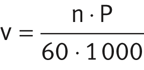
| v | m/s |
Carriage unit velocity |
| n | min–1 |
Spindle speed |
| P | mm |
Spindle pitch. |
Diagrams
The diagram show the relationship for individual series and sizes between the critical speed and the spindle length, ➤ Figure. The diagram takes account of the effective length (BL) of the bellows cover. Definition of the effective length, see link.
The diagram is valid for linear actuators with and without spindle supports, ➤ Figure.
ATTENTION
The values apply to a ball screw drive operating in a tensile direction.
Maximum permissible spindle speed

Kinematic operating limits
Maximum velocities are determined as a function of the critical spindle speed, see table. The limiting speed of the bearings can also restrict the spindle speed and thus the velocity.
Kinematic operating limits
|
Actuator |
Acceleration a |
Maximum velocity v |
Maximum spindle speed n |
|---|---|---|---|
|
m/s2 |
m/s |
min–1 |
|
|
MKUVE15-160-KGT/5-F |
20 |
0,25 |
3 000 |
|
MKUVE15-160-KGT/5-FM |
10 |
||
|
MKUVE15-160-KGT/10-F |
20 |
0,63 |
3 800 ** |
|
MKUVE15-160-KGT/10-FM |
10 |
||
|
MKUVE15-160-KGT/50-F |
20 |
2,5 |
3 000 |
|
MKUVE20-200-KGT/5-F |
20 |
0,29 |
3 500 ** |
|
MKUVE20-200-KGT/5-FM |
10 |
||
|
MKUVE20-200-KGT/10-F |
20 |
0,5 |
3 000 |
|
MKUVE20-200-KGT/10-FM |
10 |
||
|
MKUVE20-200-KGT/20-F |
20 |
1,16 |
3 500 ** |
|
MKUVE20-200-KGT/50-F |
20 |
2,9 |
3 500 ** |
|
MKUSE25-200-KGT/5-M |
20 |
0,215 |
2 600 ** |
|
MKUSE25-200-KGT/5-MM |
10 |
||
|
MKUSE25-200-KGT/10-M |
20 |
0,43 |
|
|
MKUSE25-200-KGT/10-MM |
10 |
||
|
MKUSE25-200-KGT/20-M |
20 |
0,86 |
|
|
MKUSE25-200-KGT/20-MM |
10 |
||
|
MKUSE25-200-KGT/40-M |
20 |
1,73 |
** Restricted by the limiting speed of the locating bearing with grease lubrication.
Mounting position and mounting arrangement
Due to their construction and the linear guidance system fitted, actuators are suitable for all mounting positions and mounting arrangements. Possible mounting positions are shown in ➤ Figure, ➤ Figure and ➤ Figure.
The actuators can be used in the “common” horizontal mounting position and also in a vertical mounting position.
Mounting of actuators with a carriage unit to one side or suspended overhead is possible. In such cases, please consult the Schaeffler engineering service.
ATTENTION
The ball screw drives fitted in these actuators are not self-locking. The carriage unit and load must be secured against autonomous travel or dropping if the actuators are used in a vertical or tilted mounting position. This can be achieved, for example, by means of a brake or counterweight. The drop guard must function in manual operation as well as in motor operation, especially if the motor has no current.
Safety guidelines, especially in relation to personal protection, must be observed.
Movable or stationary carriage unit

Mounting positions

Mounting positions

Mounting
In most applications, an actuator is mounted in two steps:
Interchange of actuator components
For the fitting and assembly of actuator components, a fitting and maintenance manual is available for each series of actuator. Please consult the Schaeffler engineering service.
Maintenance
Failure to carry out maintenance, incorrect maintenance, assembly errors and lubrication errors as well as inadequate protection against contamination can lead to premature failure of actuators.
Maintenance work is restricted in general to relubrication, cleaning and regular visual inspection for damage.
Maintenance intervals, especially the intervals between relubrication, are influenced by the following factors:
ATTENTION
Guidance parts relevant to function must be greased and supplied with lubricant via appropriate lubrication points.
Cleaning
If heavy contamination is present, actuators must be cleaned in order to ensure reliable function. Suitable cleaning tools include paintbrushes, soft brushes and soft cloths.
ATTENTION
Abrasives, petroleum ether and oils must not be used.
Accuracy
Length tolerances
The length tolerances of actuators are shown in ➤ Figure and the table. The data are valid for all actuators described in this chapter.
Length tolerances

Tolerances
|
Total length of actuator Ltot |
Tolerance |
|||
|---|---|---|---|---|
|
mm |
mm |
|||
|
Ltot < |
1 000 |
±2 |
||
|
1 000 |
≦ |
Ltot < |
2 000 |
±3 |
|
2 000 |
≦ |
Ltot < |
4 000 |
±4 |
|
4 000 |
≦ |
Ltot |
±5 |
|
Straightness of support rails
The support rails of the actuators are precision straightened and the tolerances are better than DIN 17615.
The tolerances are arithmetic mean values and are stated for individual series and sizes, see table.
Tolerances
|
Length L2 of support rail |
MKUVE15..-KGT MKUVE20..-KGT |
MKUSE25..-KGT |
|||||||
|---|---|---|---|---|---|---|---|---|---|
|
t2 |
t3 |
Torsion |
t2 |
t3 |
Torsion |
||||
|
mm |
mm |
mm |
mm |
mm |
mm |
mm |
|||
|
L2 ≦ |
1 000 |
0,4 |
0,3 |
0,8 |
0,4 |
0,3 |
0,5 |
||
|
1 000 |
< |
L2 ≦ |
2 000 |
0,8 |
0,5 |
1 |
0,8 |
0,5 |
1 |
|
2 000 |
< |
L2 ≦ |
3 000 |
1,2 |
0,7 |
1,2 |
1,2 |
0,7 |
1,5 |
|
3 000 |
< |
L2 ≦ |
4 000 |
1,5 |
1 |
1,6 |
1,5 |
1 |
2 |
|
4 000 |
< |
L2 ≦ |
5 000 |
1,9 |
1,2 |
1,8 |
1,9 |
1,2 |
2,5 |
|
5 000 |
< |
L2 ≦ |
5 850 |
2,5 |
1,5 |
2 |
2,5 |
1,5 |
3 |
➤ Figure shows the method for determining the straightness of the support rail.
Measurement method for straightness tolerances

Pitch accuracy of spindle
The pitch accuracies of rolled ball screw spindles for the individual series and sizes are given in the table.
Standard actuators are fitted single nuts with clearance where the axial clearance is dependent on the pitch. Where higher accuracy requirements are present, it is possible in the case of many spindle pitch to obtain actuators with a preloaded (clearance-free) double nut.
ATTENTION
In the case of standard actuators, the nut unit (double nut) can only be preloaded clearance-free if the spindle pitch P is less than the nominal diameter d0 of the spindle.
Designs of spindle and spindle nut
|
Designation |
Spindle |
Spindle nut |
|||
|---|---|---|---|---|---|
|
⌀ d0 |
P |
Pitch |
Suffix |
Axial clearance |
|
|
max. |
|||||
|
mm |
mm |
μm/300 mm |
mm |
||
|
MKUVE15-160-KGT |
16 |
5 |
50 |
F |
0,05 |
|
FM |
Preloaded |
||||
|
10 |
F |
0,05 |
|||
|
FM |
Preloaded |
||||
|
50 |
100 |
F |
0,05 |
||
|
MKUVE20-200-KGT |
20 |
5 |
50 |
F |
0,05 |
|
FM |
Preloaded |
||||
|
10 |
F |
0,05 |
|||
|
FM |
Preloaded |
||||
|
20 |
F |
0,05 |
|||
|
50 |
|||||
|
MKUSE25-200-KGT |
32 |
5 |
50 |
M |
0,05 |
|
MM |
Preloaded |
||||
|
10 |
M |
0,05 |
|||
|
MM |
Preloaded |
||||
|
20 |
M |
0,05 |
|||
|
MM |
Preloaded |
||||
|
40 |
M |
0,05 |
|||
Tandem actuators with ball screw drive
Features
Tandem actuators MDKUVE..-KGT and MDKUSE..-KGT comprise:
- a carriage unit
- two linear recirculating ball bearing and guideway assemblies
- a support rail
- a ball screw drive available with various pitch values
- one locating bearing and non-locating bearing unit
- two sets of bellows.
- support rail unit comprising carrier profile and guideway
- support spacings up to 5 850 mm
- introduction of the load at the centre of the carriage unit if this is at the centre point between the bearing points.
Actuators MDKUVE..-KGT and MDKUSE..-KGT correspond substantially in their basic design and technical characteristics to the actuators MKUVE..-KGT and MKUSE..-KGT. The features of tandem actuators substantially match the features of linear actuators.
Tandem actuators are suitable for high loads and high moments about all three axes.
The carriage unit of the tandem actuator is guided on two parallel guideways each with two carriages arranged in series.
Designs
Tandem actuators MDKUVE..-KGT and MDKUSE..-KGT are available in various designs, see table.
Available designs
|
Suffix |
Description |
Design |
|---|---|---|
|
‒ |
One driven carriage unit |
Basic design |
|
SPU |
One spindle support |
Standard |
|
2SPU |
Two spindle supports |
Standard |
|
WN2 |
Second, non-driven carriage unit |
Standard |
|
N |
Fixing slots in carriage unit |
Standard |
|
OA |
Without ball screw drive |
Standard |
Carriage unit
The carriage unit in series MDKUVE..-KGT and MDKUSE..-KGT comprises a carriage housing made from anodised profiled aluminium, a lubrication distributor and the two KWVE or KWSE carriages of the linear recirculating ball bearing and guideway assembly, ➤ Figure and table.
If higher moment loads must be supported, the actuator is available with a second, non-driven carriage unit. It is connected to the driven carriage unit by means of the adjacent construction.
Lengths of carriage units
|
Series |
Carriage unit length |
Suffix |
|---|---|---|
|
mm |
||
|
MDKUVE15..-KGT |
240 |
240 |
|
MDKUVE25..-KGT |
365 |
365 |
|
MDKUSE25..-KGT |
365 |
365 |
|
MDKUVE35..-KGT |
500 |
500 |
|
MKKUVE20..-KGT |
200 |
200 |
Carriage unit

Spindle support
Actuators MDKUVE15..-KGT with a total length of more than 1 000 mm, MDKUVE25..-KGT and MDKUSE25..-KGT with a total length of more than 1 400 mm and MDKUVE35..-KGT with a total length of more than 1 750 mm can be fitted with movable spindle supports (suffix SPU or 2SPU).
Mechanical accessories
A large number of accessories are available for tandem actuators with monorail guidance system and ball screw drive. The allocation of accessories is valid if the data match the Technical principles and the Design and safety guidelines, link.
Allocation
|
Linear actuator / size |
MDKUVE..-KGT-N |
15 |
25 |
35 |
|
|---|---|---|---|---|---|
|
MDKUSE..-KGT-N |
25 |
||||
|
Fixing brackets |
|||||
|
WKL-48×48×35 |
|
|
‒ |
||
|
WKL-65×65×30-N |
|
|
‒ |
||
|
WKL-65×65×35 |
|
|
‒ |
||
|
WKL-65×65×35-N |
|
|
‒ |
||
|
WKL-90×90×35-N |
|
|
|
||
|
WKL-98×98×35 |
‒ |
|
‒ |
||
|
Clamping lugs |
|||||
|
SPPR-22×20 |
|
‒ |
‒ |
||
|
SPPR-26×30 |
‒ |
|
‒ |
||
|
SPPR-28×30 |
|
|
‒ |
||
|
SPPR-31×30 |
‒ |
‒ |
|
||
|
SPPR-34×36 |
‒ |
‒ |
|
||
|
T-nuts |
|||||
|
|
MU-DIN 508 M4×5 |
|
‒ |
‒ |
|
|
MU-M3×5
|
|
‒ |
‒ |
||
|
MU-DIN 508 M6×8 |
|
|
‒ |
||
|
MU-M4×8
|
|
|
‒ |
||
|
MU-DIN 508 M8×10 |
‒ |
|
|
||
|
MU-M6×10
|
‒ |
|
|
||
|
T-nuts made from corrosion-resistant steel |
|||||
|
MU-DIN 508 M4×5-RB |
|
‒ |
‒ |
||
|
MU-DIN 508 M6×8-RB |
|
|
‒ |
||
|
MU-DIN 508 M8×10-RB |
‒ |
|
|
||
|
T-bolts |
|||||
|
SHR-DIN 787 M4×5×25 |
|
‒ |
‒ |
||
|
SHR DIN 787-M8×8×32 |
|
|
‒ |
||
|
SHR DIN 787-M10×10×40 |
‒ |
|
|
||
|
Rotatable T-nuts |
|||||
|
|
MU-M3×5-RHOMBUS |
|
‒ |
‒ |
|
|
MU-M4×8-RHOMBUS |
|
|
‒ |
||
|
MU-M6×8-RHOMBUS |
|
|
‒ |
||
|
MU-M8×10-RHOMBUS |
‒ |
|
|
||
|
|
Suitable. |
Allocation
|
Linear actuator / size |
MKUVE..-KGT-N |
15 |
25 |
35 |
|
|---|---|---|---|---|---|
|
MKUSE..-KGT-N |
25 |
||||
|
Positionable T-nuts |
|||||
|
|
MU-M4×5-POS |
|
‒ |
‒ |
|
|
MU-M5×5-POS |
|
‒ |
‒ |
||
|
MU-M4×8-POS |
|
|
‒ |
||
|
MU-M5×8-POS |
|
|
‒ |
||
|
MU-M6×8-POS |
|
|
‒ |
||
|
MU-M8×8-POS |
|
|
‒ |
||
|
Hexagon nuts |
|||||
|
MU-ISO 4032 M5 |
|
‒ |
‒ |
||
|
MU-ISO 4032 M8 |
|
|
|
||
|
MU-ISO 4032 M10 |
‒ |
|
|
||
|
T-strips |
|||||
|
LEIS-M4/5-T-NUT-SB-ST |
|
‒ |
‒ |
||
|
LEIS-M4/5-T-NUT-HR-ALU |
|
‒ |
‒ |
||
|
LEIS-M6/8-T-NUT-SB-ST |
|
|
‒ |
||
|
LEIS-M8/8-T-NUT-SB-ST |
|
|
‒ |
||
|
LEIS-M6/8-T-NUT-HR-ST |
|
|
‒ |
||
|
LEIS-M6/8-T-NUT-HR-ALU |
|
|
‒ |
||
|
LEIS-M4/5-T-NUT-ST |
|
|
‒ |
||
|
LEIS-M6/8-T-NUT-ST |
|
|
‒ |
||
|
LEIS-M8/10-T-NUT-ST |
‒ |
|
|
||
|
Connector sets (parallel connectors) |
|||||
|
VBS-PVB8 |
|
|
‒ |
||
|
VBS-PVB10 |
‒ |
|
|
||
|
VBS-PVB8/10 |
|
|
|
||
|
Slot closing strips |
|||||
|
NAD-5×5,7 |
|
‒ |
‒ |
||
|
NAD-8×4,5 |
|
|
‒ |
||
|
NAD-8×11,5 |
|
|
‒ |
||
|
NAD-10×6,5 |
‒ |
|
|
||
|
|
Suitable. |
|
|
Suitable and T-strips must already have been inserted at the time of despatch. |
Design and safety guidelines
The following pages describe exclusively the differences between the tandem actuators and the linear actuators.
Deflection
The deflection of tandem actuators is essentially dependent on the support spacing, the rigidity of the support rail, the adjacent construction and the bearing arrangement. As the rigidity of these components increases, the deflection of the support rail is reduced.
Diagrams
The diagram values are determined for a bearing arrangement or clamping which is in theory infinitely rigid and are subdivided into locating/non-locating and locating/locating bearing arrangements.
The deflection of the support rail is valid under the following conditions:
Deflection about the z axis

Deflection about the z axis

Deflection about the y axis

Deflection about the y axis

Deflection about the z axis

Deflection about the z axis

Deflection about the y axis

Deflection about the y axis

Deflection about the z axis

Deflection about the z axis

Deflection about the y axis

Deflection about the y axis

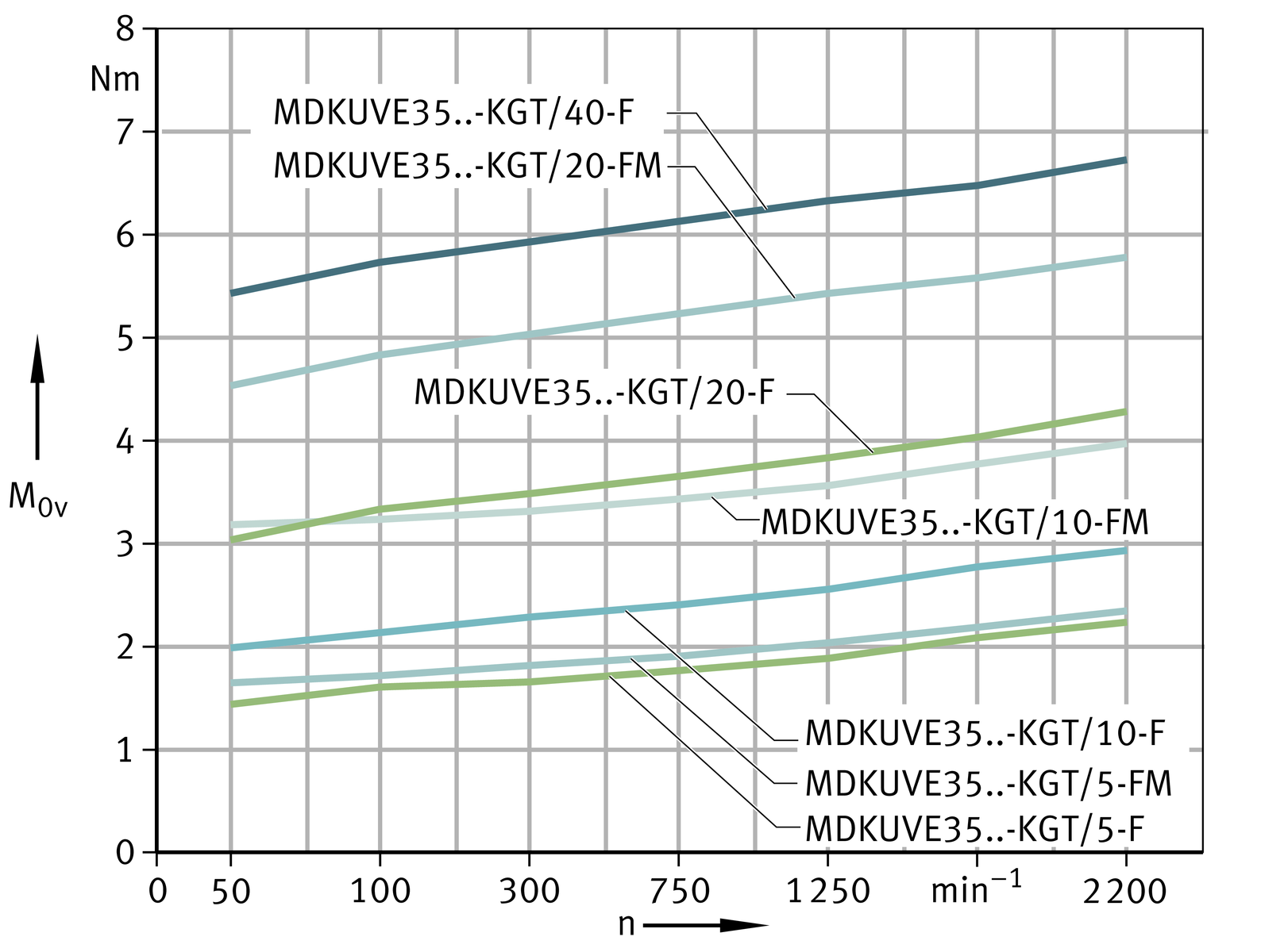
Idling drive torque
The idling drive torque M0 of linear actuators with screw drive is calculated as a function of the spindle speed and the horizontal (M0h) or vertical (M0v) mounting position. The idling drive torque increases with increasing travel velocity.
Idling drive torque Horizontal mounting position

Idling drive torque Vertical mounting position
Idling drive torque
Horizontal mounting position
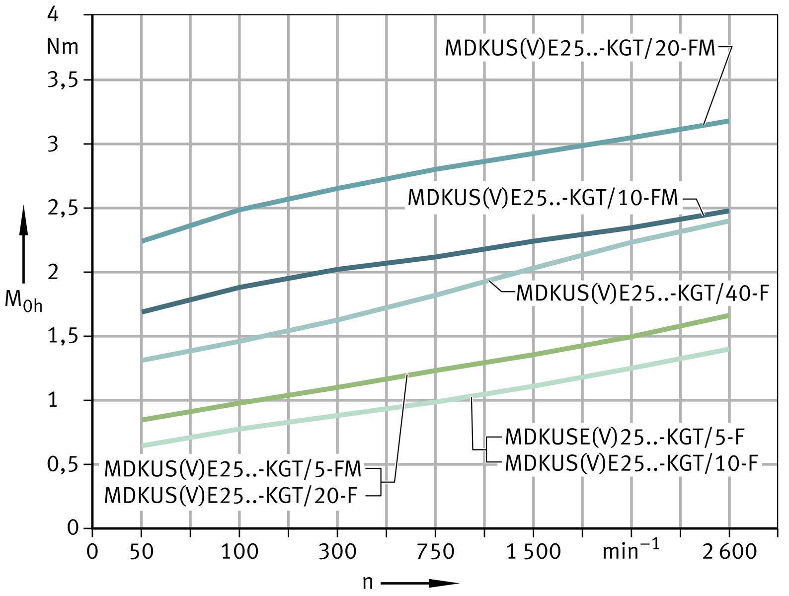
Idling drive torque
Vertical mounting position

Idling drive torque Horizontal mounting position
Idling drive torque Vertical mounting position
Length calculation of tandem actuators
The length calculation of tandem actuators is based on the required effective stroke length NH . The effective stroke length NH must be increased by the addition of safety spacing values on both sides of the travel distance.
The total length Ltot of actuators is determined from the support rail length L2 and the lengths of the end plates L4 and L5. If two carriage units are present, both carriage unit lengths L and the spacing Lx1 must be taken into consideration.
Parameters for length calculation
| GH | mm |
Total stroke length |
| NH | mm |
Effective stroke length |
| S | mm |
Safety spacing, see table |
| L | mm |
Length of carriage plate |
| L2 | mm |
Length of support rail |
| L4 | mm |
Length of end plate |
| L5 | mm |
Length of end plate |
| Ltot | mm |
Total length of actuator |
| Lx1 | mm |
Spacing between two carriage units |
| BL | mm |
Effective length of bellows |
| FBL |
Effective length factor according to actuator type. |
Total stroke length
The total stroke length GH is determined from the required effective stroke length and the safety spacings, which must correspond to at least the spindle pitch P.
Support rails
Actuators with monorail guidance system and ball screw drive are only available with a single-piece support rail. The maximum length of a support rail is 5 850 mm.
Spacing Lx1 between carriage units
The minimum spacing Lx1 min between two carriage units is 20 mm.
Total length Ltot and support rail length L2
The following ➤ equtions are designed for one and two carriage units. The parameters and their position can be found in ➤ Figure, ➤ Figure and the table. If more than two carriage units are present, please contact us.
Length parameters for one carriage unit
One carriage unit with bellows
Total length
Length parameters for two carriage units
Two carriage units with bellows
Total length
Length parameters
|
Designation |
L |
L4 |
L5 |
S |
FBL |
|---|---|---|---|---|---|
|
mm |
mm |
mm |
mm |
||
|
MDKUVE15-240-KGT/5-N |
240 |
28 |
28 |
5 |
1,15 |
|
MDKUVE15-240-KGT/10-N |
10 |
||||
|
MDKUVE15-240-KGT/20-N |
20 |
||||
|
MDKUVE15-240-KGT/50-N |
50 |
||||
|
MDKUVE15-240-KGT-OA-N |
240 |
‒ |
28 |
10 |
|
|
MDKUVE25-365-KGT/5-N |
365 |
33 |
28 |
5 |
1,18 |
|
MDKUVE25-365-KGT/10-N |
10 |
||||
|
MDKUVE25-365-KGT/20-N |
20 |
||||
|
MDKUVE25-365-KGT/40-N |
40 |
||||
|
MDKUVE25-365-KGT-OA-N |
365 |
‒ |
28 |
10 |
|
|
MDKUSE25-365-KGT/5-N |
365 |
33 |
28 |
5 |
1,18 |
|
MDKUSE25-365-KGT/10-N |
10 |
||||
|
MDKUSE25-365-KGT/20-N |
20 |
||||
|
MDKUSE25-365-KGT/40-N |
40 |
||||
|
MDKUSE25-365-KGT-OA-N |
365 |
‒ |
28 |
10 |
|
|
MDKUVE35-500-KGT/5-N |
500 |
48 |
30 |
5 |
1,1 |
|
MDKUVE35-500-KGT/10-N |
10 |
||||
|
MDKUVE35-500-KGT/20-N |
20 |
||||
|
MDKUVE35-500-KGT/40-N |
40 |
||||
|
MDKUVE35-500-KGT-OA-N |
500 |
‒ |
30 |
10 |
Effective length of bellows
The effective length of bellows is the length occupied by the bellows in the fully compressed state. Calculation is based on the total stroke length GH , ➤ Figure, ➤ equtions and table.
Effective length calculation
| BL | mm |
Effective length of bellows |
| GH | mm |
Total stroke length |
| FBL | – |
Effective length factor according to actuator type, see table. |
Mass calculation
The total mass of an actuator is calculated from the mass of the actuator without a carriage unit, the carriage unit and the special design: second carriage unit (WN2), ➤ Figure. Insert the values from the table in the following ➤ equation. The values mLAW and mBOL are mandatory.
Basic and additional designs
Values for mass calculation
|
Designation |
Mass |
||
|---|---|---|---|
|
Carriage unit |
Design WN2 |
Actuator without carriage unit |
|
|
mLAW |
m3 |
mBOL |
|
|
≈kg |
≈kg |
≈kg |
|
|
MDKUVE15-240-KGT..-N |
4,61 |
4,2 |
(Ltot – 56) · 0,0177 + 3,51 |
|
MDKUVE15-240-KGT-OA..-N |
4,2 |
4,2 |
(Ltot – 56) · 0,0177 + 2,53 |
|
MDKUVE25-365-KGT..-N |
13,04 |
11,48 |
(Ltot – 61) · 0,0372 + 7,56 |
|
MDKUVE25-365-KGT-OA..-N |
11,48 |
11,48 |
(Ltot – 56) · 0,0372 + 5,36 |
|
MDKUSE25-365-KGT..-N |
12,84 |
11,28 |
(Ltot – 61) · 0,0380 + 7,56 |
|
MDKUSE25-365-KGT-OA..-N |
11,28 |
11,28 |
(Ltot – 56) · 0,0380 + 5,36 |
|
MDKUVE35-500-KGT..-N |
34,7 |
28,41 |
(Ltot – 78) · 0,0797 + 22,21 |
|
MDKUVE35-500-KGT-OA..-N |
30 |
28,41 |
(Ltot – 60) · 0,0797 + 13,21 |
Lubrication
The information on the lubrication of tandem actuators matches the information on the lubrication of linear actuators. The only differences are in the relubrication quantities and relubrication points.
Relubrication quantities
Relubrication should be carried out wherever possible with several partial quantities at various times instead of the complete quantity at the time of the relubrication interval. Relubrication quantities, see table.
Grease quantities
|
Tandem actuator |
Relubrication quantity per driven carriage unit, lubrication nipple and longitudinal face |
Relubrication quantity per non-driven carriage unit, lubrication nipple and longitudinal face |
||
|---|---|---|---|---|
|
Drive |
Non-locating bearing side |
Drive |
Non-locating bearing side |
|
|
≈g |
≈g |
≈g |
≈g |
|
|
MDKUVE15-240-KGT/5-F MDKUVE15-240-KGT/5-FM MDKUVE15-240-KGT/10-F MDKUVE15-240-KGT/10-FM MDKUVE15-240-KGT/20-F MDKUVE15-240-KGT/50-F |
2 to 3 |
1 to 2 |
1 to 2 |
1 to 2 |
|
MDKUVE25-365-KGT/5-F MDKUVE25-365-KGT/5-FM MDKUVE25-365-KGT/10-F MDKUVE25-365-KGT/10-FM MDKUVE25-365-KGT/20-F MDKUVE25-365-KGT/20-FM MDKUVE25-365-KGT/40-F |
6 to 9 |
3 to 5 |
3 to 5 |
3 to 5 |
|
MDKUSE25-365-KGT/5-F MDKUSE25-365-KGT/5-FM MDKUSE25-365-KGT/10-F MDKUSE25-365-KGT/10-FM MDKUSE25-365-KGT/20-F MDKUSE25-365-KGT/20-FM MDKUSE25-365-KGT/40-F |
8 to 12 |
6 to 8 |
6 to 8 |
6 to 8 |
|
MDKUVE35-500-KGT/5-F MDKUVE35-500-KGT/5-FM MDKUVE35-500-KGT/10-F MDKUVE35-500-KGT/10-FM MDKUVE35-500-KGT/20-F MDKUVE35-500-KGT/20-FM MDKUVE35-500-KGT/40-F |
7 to 11 |
4 to 6 |
4 to 6 |
4 to 6 |
Relubrication points
Each carriage unit in a tandem actuator with linear recirculating ball bearing and guideway assembly and ball screw drive is equipped with four funnel type lubrication nipples according to DIN 3405‑A M6. It can be lubricated from either the left or right side. On the drive side, lubrication nipples are located to the left and right longitudinal sides of the carriage unit through which the front carriages and spindle nut can be relubricated. The carriages on the non-locating bearing side can be relubricated via a further countersunk lubrication nipple on each longitudinal side of the carriage unit, ➤ Figure.
Lubrication points

ATTENTION
During lubrication of actuators, all lubrication points on one longitudinal side of a carriage unit must always be provided with lubricant.
Position of relubrication points
|
Designation |
Mounting dimensions |
|||
|---|---|---|---|---|
|
S56 |
h56 |
l56 |
l57 |
|
|
mm |
mm |
mm |
mm |
|
|
MDKUVE15..-KGT..-N |
15 |
20 |
70,3 |
99,4 |
|
MDKUVE25..-KGT..-N |
15 |
28 |
95,85 |
173,3 |
|
MDKUSE25..-KGT..-N |
15 |
28 |
82,8 |
199,4 |
|
MDKUVE35..-KGT..-N |
36 |
30 |
122,5 |
255 |
Position of relubrication points

T-slots
The T-slots in the support rail and the carriage unit are designed for T-bolts according to DIN 787 and T-nuts according to DIN 508, ➤ Figure.
Sizes of T-slots in support rail and carriage unit

Dimensions of T-slots
|
Designation |
Support rail |
Carriage unit |
||
|---|---|---|---|---|
|
Lateral |
Bottom |
Top |
Lateral |
|
|
MDKUVE15..-KGT |
|
|
|
|
|
MDKUSE15..-KGT |
|
‒ |
‒ |
‒ |
|
MDKUVE25..-KGT |
|
|
|
|
|
MDKUSE25..-KGT |
|
|
|
|
|
MDKUVE35..-KGT |
|
|
|
|
Filling openings
The filling openings in the non-locating bearing units of the tandem actuators are used for the insertion of T-nuts and T-bolts in the T‑slots of the support rail. The filling openings are arranged at the centre of the carriage unit.
Connectors for switching tags
Switching tags can be screw mounted to the carriage unit in order to activate switches in the adjacent construction. The position and size are dependent on the size, ➤ Figure and table.
Connectors for switching tags on the carriage unit

Mounting dimensions for switching tags
|
Designation |
T-slot |
Mounting |
|---|---|---|
|
h58 |
||
|
mm |
||
|
MDKUVE15..-KGT |
|
19,3 |
|
MDKUVE25..-KGT |
|
23 |
|
MDKUSE25..-KGT |
|
23 |
|
MDKUVE35..-KGT |
|
28 |
Maximum permissible spindle speed
The data on the maximum permissible spindle speed of the tandem actuators matches the data for linear actuators.
Diagram
The diagram is valid for tandem actuators with and without spindle supports, ➤ Figure.
Maximum permissible spindle speed

Kinematic operating limits
|
Actuator |
Acceleration a |
Maximum velocity v |
Maximum spindle speed n |
|---|---|---|---|
|
m/s2 |
m/s |
min–1 |
|
|
MDKUVE15-240-KGT/5-F |
20 |
0,29 |
3 500 |
|
MDKUVE15-240-KGT/5-FM |
10 |
||
|
MDKUVE15-240-KGT/10-F |
20 |
0,5 |
3 000 |
|
MDKUVE15-240-KGT/10-FM |
10 |
||
|
MDKUVE15-240-KGT/20-F |
20 |
1,16 |
3 500 |
|
MDKUVE15-240-KGT/50-F |
20 |
2,9 |
3 500 |
|
MDKUVE25-365-KGT/5-F |
20 |
0,215 |
2 600 ** |
|
MDKUVE25-365-KGT/5-FM |
10 |
||
|
MDKUVE25-365-KGT/10-F |
20 |
0,43 |
|
|
MDKUVE25-365-KGT/10-FM |
10 |
||
|
MDKUVE25-365-KGT/20-F |
20 |
0,86 |
|
|
MDKUVE25-365-KGT/20-FM |
10 |
||
|
MDKUVE25-365-KGT/40-F |
20 |
1,73 |
|
|
MDKUSE25-365-KGT/5-F |
20 |
0,215 |
2 600 ** |
|
MDKUSE25-365-KGT/5-FM |
10 |
||
|
MDKUSE25-365-KGT/10-F |
20 |
0,43 |
|
|
MDKUSE25-365-KGT/10-FM |
10 |
||
|
MDKUSE25-365-KGT/20-F |
20 |
0,86 |
|
|
MDKUSE25-365-KGT/20-FM |
10 |
||
|
MDKUSE25-365-KGT/40-F |
20 |
1,73 |
|
|
MDKUVE35-500-KGT/5-F |
20 |
0,18 |
2 200 ** |
|
MDKUVE35-500-KGT/5-FM |
10 |
||
|
MDKUVE35-500-KGT/10-F |
20 |
0,36 |
|
|
MDKUVE35-500-KGT/10-FM |
10 |
||
|
MDKUVE35-500-KGT/20-F |
20 |
0,73 |
|
|
MDKUVE35-500-KGT/20-FM |
10 |
||
|
MDKUVE35-500-KGT/40-F |
20 |
1,46 |
** Restricted by the limiting speed of the locating bearing with grease lubrication.
Accuracy
Length tolerances
The information on the length tolerance of tandem actuators matches the information on the length tolerance of linear actuators.
Straightness of support rails
The information on the straightness of the support rails of tandem actuators matches the information on the straightness of the support rails of linear actuators. Values for the straightness tolerances of support rails of tandem actuators, see table.
Tolerances
|
Length L2 of support rail |
MDKUVE15..-KGT |
MDKUSE25..-KGT MDKUVE25..-KGT |
MDKUVE35..-KGT |
|||||||||
|---|---|---|---|---|---|---|---|---|---|---|---|---|
|
t2 |
t3 |
Torsion |
t2 |
t3 |
Torsion |
t2 |
t3 |
Torsion |
||||
|
mm |
mm |
mm |
mm |
mm |
mm |
mm |
mm |
mm |
mm |
|||
|
L2 ≦ |
1 000 |
0,6 |
0,5 |
0,5 |
0,8 |
0,7 |
0,5 |
0,8 |
0,7 |
0,8 |
||
|
1 000 |
< |
L2 ≦ |
2 000 |
1 |
0,7 |
1 |
1,2 |
0,9 |
1 |
1,6 |
1,4 |
1,2 |
|
2 000 |
< |
L2 ≦ |
3 000 |
1,4 |
0,9 |
1,5 |
1,6 |
1,1 |
1,5 |
2,4 |
2,1 |
2 |
|
3 000 |
< |
L2 ≦ |
4 000 |
1,7 |
1,2 |
2 |
1,9 |
1,4 |
2 |
3,2 |
2,8 |
2,4 |
|
4 000 |
< |
L2 ≦ |
5 000 |
2,1 |
1,4 |
2,5 |
2,3 |
1,6 |
2,5 |
4 |
3,5 |
2,8 |
|
5 000 |
< |
L2 ≦ |
5 850 |
2,7 |
1,7 |
3 |
2,9 |
1,9 |
3 |
4,8 |
4,2 |
3,3 |
Measurement method for straightness tolerances

Pitch accuracy of spindle
The information on the pitch accuracy of the spindle in tandem actuators matches the information on the pitch accuracy of the spindle in linear actuators. Values for the ball screw drive in tandem actuators, see table.
Designs of spindle and spindle nut
|
Designation |
Spindle |
Spindle nut |
|||
|---|---|---|---|---|---|
|
⌀ d0 |
P |
Pitch accuracy |
Suffix |
Axial clearance |
|
|
max. |
|||||
|
mm |
mm |
μm/300 mm |
mm |
||
|
MDKUVE15-240-KGT |
20 |
5 |
50 |
F |
0,05 |
|
FM |
Preloaded |
||||
|
10 |
F |
0,05 |
|||
|
FM |
Preloaded |
||||
|
20 |
F |
0,05 |
|||
|
50 |
|||||
|
MDKUVE25-365-KGT MDKUSE25-365-KGT |
32 |
5 |
50 |
F |
0,05 |
|
FM |
Preloaded |
||||
|
10 |
F |
0,05 |
|||
|
FM |
Preloaded |
||||
|
20 |
F |
0,05 |
|||
|
FM |
Preloaded |
||||
|
40 |
F |
0,05 |
|||
|
MDKUVE35-500-KGT |
40 |
5 |
50 |
F |
0,05 |
|
FM |
Preloaded |
||||
|
10 |
F |
0,05 |
|||
|
FM |
Preloaded |
||||
|
20 |
F |
0,05 |
|||
|
FM |
Preloaded |
||||
|
40 |
F |
0,05 |
|||
Clamping actuator with ball screw drive
Features
Actuators MKKUVE..-KGT correspond in their basic design and technical characteristics to the actuators MKUVE..-KGT. The features of clamping actuators substantially match the features of linear actuators. The differences are described on the following pages.
In the case of clamping actuators, the carriage units move in synchronised opposing directions.
Spindle support
Actuators MKKUVE20..-KGT/5 with a total length of more than 2 000 mm can be fitted with movable spindle supports (suffix SPU).
Designs
Clamping actuators of series MKKUVE..-KGT are available in various designs, see table. The possible designs and combinations vary according to the size and actuator type.
Available designs
|
Suffix |
Description |
Design |
|---|---|---|
|
‒ |
Two carriage units moving in opposing directions |
Basic design |
|
N |
Fixing slots in carriage unit |
Standard |
|
SPU |
One spindle support |
Standard |
Special designs
Special designs are available by agreement. Examples of these are clamping actuators:
- with a linear recirculating ball bearing and guideway assembly and ball screw drive with anti-corrosion protection
- with bellows resistant to welding beads
- without bellows
- with an extended carriage unit
- with compressed air connections in the support rail
- with special machining.
Ball screw drive
The configured “right/left” thread of the spindle is rolled, has a pitch value of 5 mm and is available with a single nut with clearance or a preloaded double nut.
Standard actuators are fitted single nuts with clearance where the axial clearance is dependent on the pitch.
The spindle is supported on the locating bearing side by an axial angular contact ball bearing ZKLF..-2RS-PE. This bearing is greased for life.
The screw drive and guidance system are protected against contamination by bellows.
One spindle support can be fitted.
Ball screw drive variants
The ball screw drive has a pitch value of P = 5 mm. The ball screw drive is available with a single nut (suffix F) or with a double nut (suffix FM).
Mechanical accessories
A large number of accessories are available for clamping actuators with monorail guidance system and ball screw drive. The allocation of accessories is valid if the data match the Technical principles and the Design and safety guidelines, link.
Allocation
|
Linear actuator / size |
MKKUVE..-KGT-N |
20 |
|
|---|---|---|---|
|
Fixing brackets |
|||
|
WKL-65×65×30-N |
|
||
|
WKL-65×65×35-N |
|
||
|
WKL-90×90×35-N |
|
||
|
Clamping lugs |
|||
|
SPPR-13,5×20 |
|
||
|
SPPR-23×30 |
|
||
|
T-nuts |
|||
|
MU-DIN 508 M6×8 |
|
||
|
MU-M4×8
|
|
||
|
T-nuts made from corrosion-resistant steel |
|||
|
MU-DIN 508 M6×8-RB |
|
||
|
T-bolts |
|||
|
SHR DIN 787-M8×8×32 |
|
||
|
Rotatable T-nuts |
|||
|
MU-M4×8-RHOMBUS |
|
||
|
MU-M6×8-RHOMBUS |
|
||
|
Positionable T-nuts |
|||
|
|
MU-M4×8-POS |
|
|
|
MU-M5×8-POS |
|
||
|
MU-M6×8-POS |
|
||
|
MU-M8×8-POS |
|
||
|
Hexagon nuts |
|||
|
MU-ISO 4032 M4 |
|
||
|
MU-ISO 4032 M8 |
|
||
|
T-strips |
|||
|
LEIS-M6/8-T-NUT-SB-ST |
|
||
|
LEIS-M8/8-T-NUT-SB-ST |
|
||
|
LEIS-M6/8-T-NUT-HR-ST |
|
||
|
LEIS-M6/8-T-NUT-HR-ALU |
|
||
|
LEIS-M6/8-T-NUT-ST |
|
||
|
Connector sets (parallel connectors) |
|||
|
VBS-PVB8 |
|
||
|
VBS-PVB8/10 |
|
||
|
Slot closing strips |
|||
|
NAD-8×4,5 |
|
||
|
NAD-8×11,5 |
|
||
|
|
Suitable. |
|
|
Suitable and T-strips must already have been inserted at the time of despatch. |
Design and safety guidelines
The following pages describe exclusively the differences between the clamping actuator and the linear actuators.
Idling drive torque
The idling drive torque M0 of clamping actuators is calculated for a constant velocity and for a horizontal (M0h) or vertical (M0v) mounting position, ➤ Figure and ➤ Figure. The idling drive torque increases with increasing travel velocity. The data in the diagrams are maximum values.
Idling drive torque
Horizontal mounting position

Idling drive torque
Vertical mounting position

Length calculation of clamping actuators
The length calculation of clamping actuators is based on the required effective stroke length NH . The effective stroke length NH must be increased by the addition of safety spacing values on both sides of the travel distance.
The total length Ltot of the clamping actuator is determined from the support rail length L2 and the lengths of the end plate L4 and end plate L5 .
Parameters for length calculation
| GH | mm |
Total stroke length |
| NH | mm |
Effective stroke length |
| S | mm |
Safety spacing, for minimum values see tables |
| L | mm |
Length of carriage plate |
| L2 | mm |
Length of support rail |
| L4 | mm |
Length of end plate |
| L5 | mm |
Length of end plate |
| Ltot | mm |
Total length of actuator |
| Lk | mm |
Spacing between the carriage units moving in opposing directions |
| BL | mm |
Effective length of bellows |
| FBL |
Effective length factor according to actuator type. |
Total stroke length
The total stroke length GH is determined from the required effective stroke length and the safety spacings, which must correspond to at least the spindle pitch P.

Support rails
Actuators with monorail guidance system and ball screw drive are only available with a single-piece support rail. The maximum length of a support rail is 5 850 mm.
Minimum spacing Lk min between carriage units
The minimum spacing Lk between the carriage units when moved together is 0,17 · GH + 20 mm.
Total length Ltot and support rail length L2
The following ➤ equtions are designed for the clamping actuator. The parameters and their position can be found in ➤ Figure and the table.
Length parameters

Support rail length with bellows
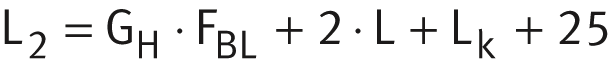
Total length
Length parameters
|
Designation |
L |
L4 |
L5 |
S |
FBL |
|---|---|---|---|---|---|
|
mm |
mm |
mm |
mm |
||
|
MKKUVE20-200-KGT/5-N |
200 |
28 |
28 |
5 |
1,09 |
Effective length of bellows
The effective length of bellows is the length occupied by the bellows in the fully compressed state. Calculation is based on the total stroke length GH , ➤ Figure, ➤ equation and table.
Effective length calculation

| BL | mm |
Effective length of bellows |
| GH | mm |
Total stroke length |
| FBL | – |
Effective length factor according to actuator type, see table. |
Mass calculation
The total mass of an actuator is calculated from the mass of the actuator without carriage units and the two carriage units. Insert the values from the table in the following ➤ equation. The values mLAW and mBOL are mandatory.

Basic design

Values for mass calculation
|
Designation |
Mass |
|
|---|---|---|
|
Carriage unit |
Actuator without carriage unit |
|
|
mLAW |
mBOL |
|
|
≈kg |
≈kg |
|
|
MKKUVE20-200-KGT..-N |
4,32 ** |
(Ltot – 56) · 0,0119 + 2,18 |
** Two carriage units.
Lubrication
The information on the lubrication of the clamping actuator matches the information on the lubrication of linear actuators. The only differences are in the relubrication quantities and relubrication points.
Relubrication quantities
Relubrication should be carried out wherever possible with several partial quantities at various times instead of the complete quantity at the time of the relubrication interval. Relubrication quantities, see table.
Grease quantities
|
Clamping actuator |
Relubrication quantity |
|---|---|
|
≈g |
|
|
MKKUVE20-200-KGT/5-F MKKUVE20-200-KGT/5-FM |
3 to 4 |
Relubrication points
The carriages and ball screw nut are relubricated via two funnel type lubrication nipples according to DIN 3405-A M6 on the longitudinal sides of each carriage unit. It can be lubricated from either the left or right side, ➤ Figure and ➤ Figure.
Lubrication points
Position of relubrication point

ATTENTION
During lubrication of actuators, all lubrication points on one longitudinal side of a carriage unit must always be provided with lubricant.
T-slots
The T-slots in the support rail and the carriage unit are designed for T-bolts according to DIN 787 and T-nuts according to DIN 508 (with the exception of T-slot size 4,5), ➤ Figure. The T-nuts and T-bolts are inserted via filling slots in the non-locating bearing unit.
Sizes of T-slots in support rail and carriage unit

Filling openings
The filling openings are located on three sides of the clamping actuator: on both sides and underneath, ➤ Figure.
Filling opening in the support rail

Connectors for switching tags
Switching tags can be screw mounted to the carriage unit in order to activate switches in the adjacent construction. The position and size in the clamping actuator are shown in ➤ Figure.
Connectors for switching tags on the carriage unit

Maximum permissible spindle speed
The information on the maximum permissible spindle speed of the clamping actuators matches the information for linear actuators.
Diagram
The diagram is valid for clamping actuators with and without spindle supports, ➤ Figure.
Maximum permissible spindle speed
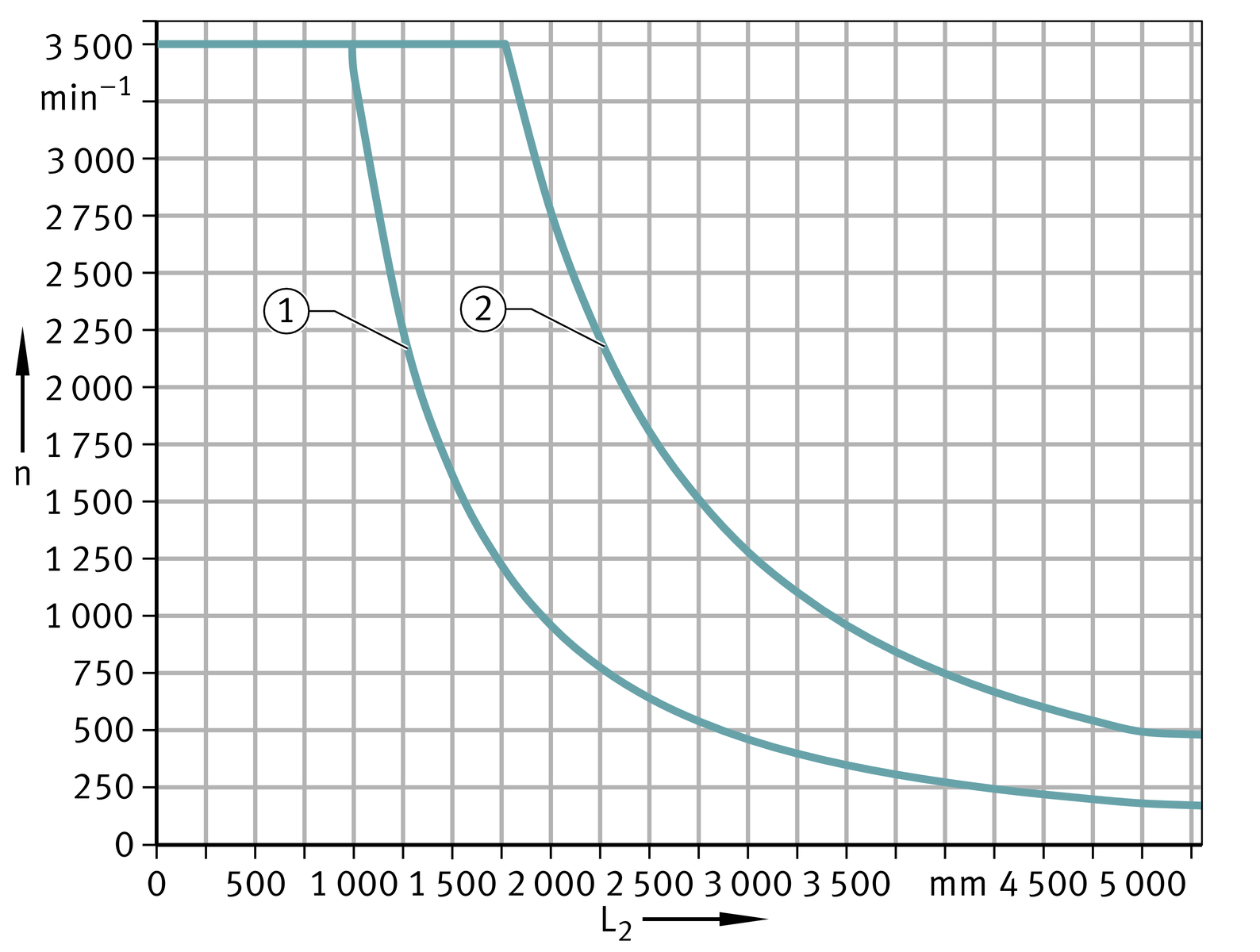
Kinematic operating limits
Maximum velocities are determined as a function of the critical spindle speed, see table.
Kinematic operating limits
|
Actuator |
Acceleration a |
Maximum velocity v |
Maximum spindle speed n |
|---|---|---|---|
|
m/s2 |
m/s |
min–1 |
|
|
MKKUVE20-200-KGT/5-F |
20 |
0,29 |
3 500 |
|
MKKUVE20-200-KGT/5-FM |
10 |
Accuracy
Length tolerances
The information on the length tolerance of the clamping actuator matches the information on the length tolerance of linear actuators.
Straightness of support rails
The information on the straightness of the support rails of the clamping actuator matches the information on the straightness of the support rails of linear actuators. Values for the straightness tolerances of support rails of clamping actuators, see table.
Tolerances
|
Length L2 of support rail |
MKKUVE20..-KGT |
|||||
|---|---|---|---|---|---|---|
|
t2 |
t3 |
Torsion |
||||
|
mm |
mm |
mm |
mm |
|||
|
L2 ≦ |
1 000 |
0,4 |
0,3 |
0,8 |
||
|
1 000 |
< |
L2 ≦ |
2 000 |
0,8 |
0,5 |
1 |
|
2 000 |
< |
L2 ≦ |
3 000 |
1,2 |
0,7 |
1,2 |
|
3 000 |
< |
L2 ≦ |
4 000 |
1,5 |
1 |
1,6 |
|
4 000 |
< |
L2 ≦ |
5 000 |
1,9 |
1,2 |
1,8 |
|
5 000 |
< |
L2 ≦ |
5 850 |
2,5 |
1,5 |
2 |
Pitch accuracy of spindle
The information on the pitch accuracy of the spindle in the clamping actuator matches the information on the pitch accuracy of the spindle in linear actuators. Values for the ball screw drive in clamping actuators, see table.
Designs of spindle and spindle nut
|
Designation |
Spindle |
Spindle nut |
||||
|---|---|---|---|---|---|---|
|
⌀ d0
|
P |
Pitch accuracy |
Single or double nut |
Suffix |
Axial clearance ** |
|
|
max. |
||||||
|
mm |
mm |
μm/300 mm |
mm |
|||
|
MKKUVE20-200-KGT |
20 |
5 |
50 |
Single |
F |
0,05 |
|
Double |
FM |
Preloaded |
||||
** Per carriage unit.