Konumunuza ait içeriği görmek için farklı bir ülke ya da bölge seçin
Amerika Birleşik Devletleri
15:36:43 GMT+0000 (Coordinated Universal Time)
Ürün bilgisi

KUVE..-B, KUVE..-B-L, KUVE..-B-N, KUVE..B-NL


KUVE..-B, KUVE..-B-L, KUVE..-B-N, KUVE..B-NL


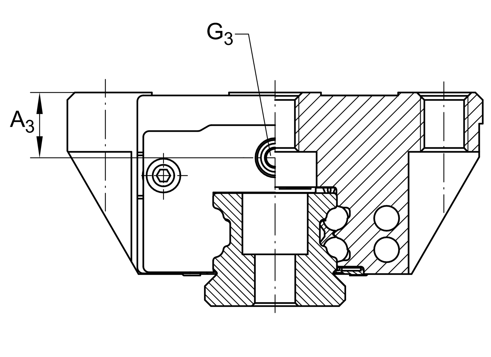
Lubrication connector on lateral face

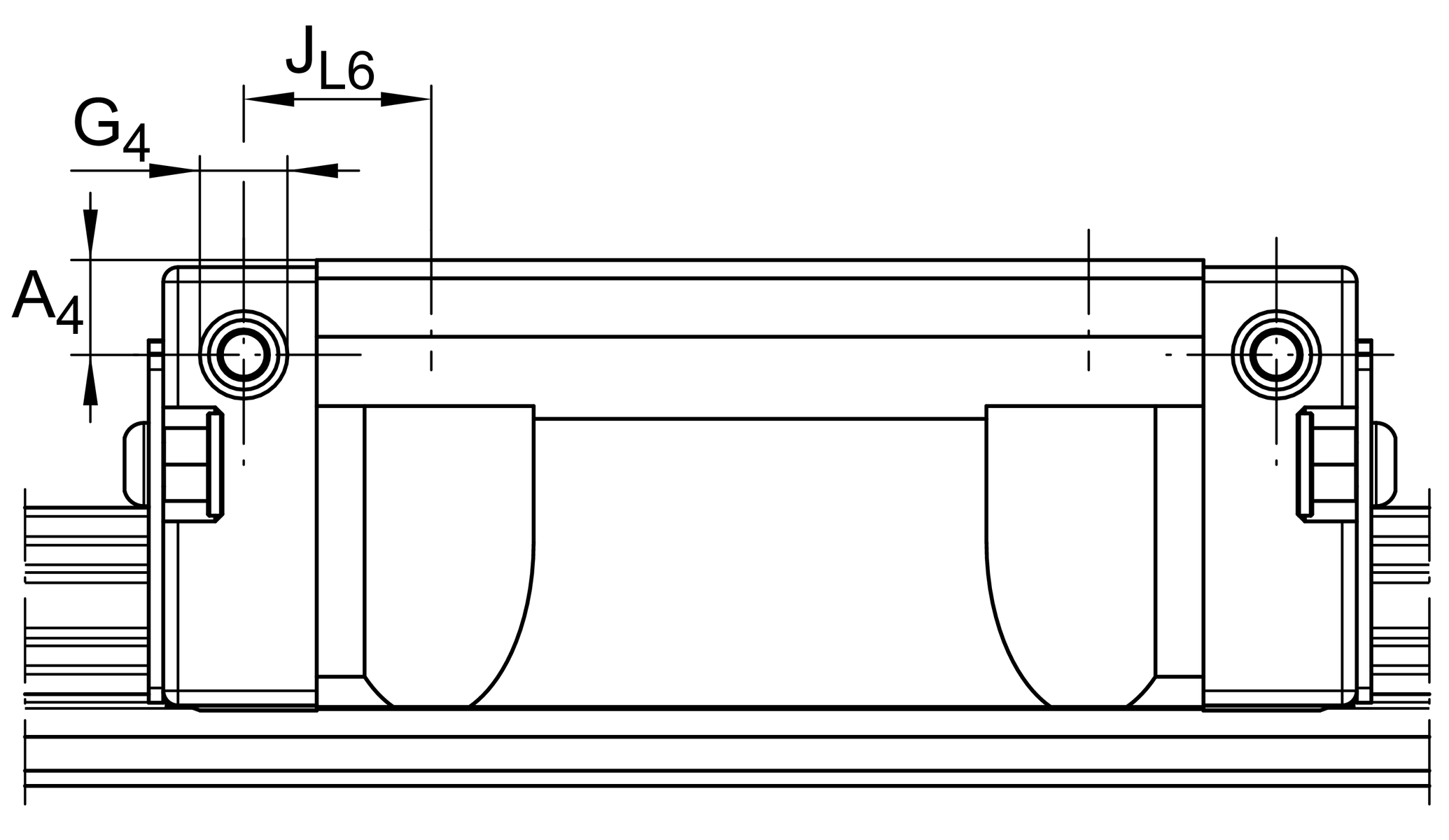
Lubrication connector on end face

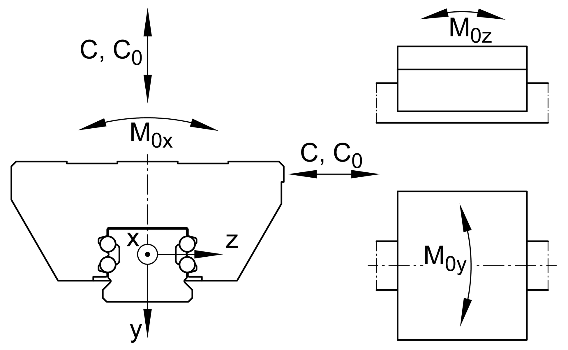
Load directions

Main Dimensions & Performance Data
| H | 30 mm | Height system |
| B | 63 mm | Width carriage |
| L | 71,4 mm | Overall length carriage |
| C | 13.100 N | Dynamic load rating 1 |
| C0 | 27.000 N | Static load rating 1 |
| M0x | 332 Nm | Static moment rating about X axis |
| M0y | 240 Nm | Static moment rating about Y axis |
| M0z | 240 Nm | Static moment rating about Z axis |
| ≈m | 0,44 kg | Ağırlık |
Mounting dimensions
| A1 | 21,5 mm | Distance from locating edge on carriage to locating edge on guideway |
| JB | 53 mm | |
| b | 20 mm | Width rail |
| A2 | 5 mm | Distance from locating edge to hole |
| L1 | 50,4 mm | |
| LS | 1,3 mm | |
| JL | 40 mm | |
| JLZ | 35 mm | |
| H1 | 4,5 mm | Free space, system dimension |
| H4 | 11 mm | |
| H5 | 5,25 mm | |
| T5 | 10 mm | Thread depth |
| T6 | 7,5 mm | |
| G2 | M6 | Fixing screws above (DIN ISO 4762-12.9) |
| G2 MA | 10 Nm | Maximum tightening torque 2 |
| K3 | M5 | Fixing screws below (DIN ISO 4762-12.9) |
| K3 MA | 10 Nm | Maximum tightening torque 2 |
| K6 | M5 | Fixing screws below (DIN ISO4762-12.9) |
| K6 MA | 10 Nm | Maximum tightening torque 3 |
| D2 | 5,5 mm | |
| A3 | 7,7 mm | Position lubrication connector |
| G3 | M5 | Lubrication connector |
| t G3 | 7 mm | Maximum permissible screw depth for lubrication connectors |
| A4 | 4,6 mm | Position lubrication connector |
| G4 | M5 | Lubrication connector |
| t G4 | 5,5 mm | Maximum permissible screw depth for lubrication connectors |
| JL6 | 9,4 mm | Position lubrication connector |
Additional information
| VMKB_065 | KWVE | Material name |
Dipnotlar
1
Calculation of basic load ratings in accordance with DIN ISO 14728-1.
Based on practical experience, it may be possible to increase the basic dynamic load rating. The basic load rating can only be transmitted fully if the whole thread length is used and the adjacent construction is dimensioned appropriately.
2
The stated torques represent maximum values for the secure transmission of forces in vibration-free, quasistatic applications (S0 = 1). We recommend that the tightening torques for the screw connection of the adjacent construction should be determined at the customer under the conditions specific to the application and operation, observing the information in VDI Guideline 2230 Part 1 (2015) and the information in this description.
3

İndirmeler:
Mevcut ürün modeliniz
| Size code | 20 | |
| Version | B | |
| Carriage design | / | Standard carriage |


